1. What Is Aluminum Die Casting?
Aluminum die casting is one of the most widely used industrial methods to produce cast aluminum parts, especially in applications where high volume, dimensional accuracy, and complex geometry are required.
As an advanced form of basic aluminum casting, die casting uses high-pressure injection and reusable steel molds to achieve consistent quality and high production efficiency.
● Quickly inject molten aluminum into a reusable steel mold (die casting mold) under high pressure and cool it in a short time, to form a part with desired shape and dimensions
● An efficient and precise metal forming method
● Specially used for mass production of aluminum parts with complex shapes, due to expensive casting equipment and molds
● Aluminum die casting is like “metal injection molding”
2. Commonly Used Die Casting Aluminum Types and Their Applications
2.1 Die Casting Aluminum
Die casting aluminum alloys are specifically developed for cast aluminum production, offering a balance between fluidity, strength, and manufacturability in basic aluminum casting processes.
● Made by smelting and casting processes with aluminum as the base, adding alloy elements such as copper, silicon, and magnesium
● Mainly exists in the form of alloy ingots
● Low density, high specific strength, good corrosion resistance and casting processability
● Ideal for manufacturing parts of various shapes
2.2 Commonly Used Die Casting Aluminum Types and Their Applications
● The commonly usedcast aluminum alloys are ADC12, A356, A360, A380, ZL102 and ZL104
● The most common cast aluminum alloy is ADC12, which has a market share of 70% in the entire cast aluminum alloy
| Table 1 – Commonly Used Die Casting Aluminum Alloys & Typical Applications | ||||
| Standards | Alloy Series | Features | Typical Grades | Typical Applications |
| China | Al-Si | ● Excellent corrosion resistance, heat resistance and weldability | ● ZL102 ● ZL104 | ● Instruments ● Water pump housings ● Lamp brackets, kitchen utensils (ZL102) ● Non-core components of power tools (ZL104) ● Tablet computer back panel (ZL104) |
| Al-Si-Cu | ● Good heat resistance ● High strength | ● ZL201 ● ZL203 | ● Engine bodies ● Cylinder blocks | |
| Al-Mg | ● Good corrosion resistance, ● High strength ● Low density | ● ZL301 ● ZL303 | ● Ship parts ● Ammonia pump bodies | |
| Al-Zn | ● Good forging performance ● High strength | ● ZL401 ● ZL402 | ● Automobile parts ● Aircraft parts ● Instrument parts | |
| Japan | Al-Si-Cu | ● Good fluidity, excellent casting performance ● Aaverage corrosion resistance | ADC12 (Chinese grade YL113; American grade ASTM A383) | ● Cylinder head cover ● Sensor bracket ● Cylinder block ● Engine mounts ● Router housing |
| American | Al-Si-Mg | ● High strength and toughness ● Good casting properties ● Corrosion resistance | A356 (Chinese grade ZL101) | ● Automobile wheel hub ● Suspension components ● Electric vehicle battery tray |
| Al-Si-Cu | ● Good casting properties ● Medium strength ● Good corrosion resistance and processability | A360 (Chinese grade YL104; Japanese grade ADC3) | ● Power structure parts with complex shapes and large sizes and large loads ● Automobile cylinder head cover ● Hydraulic valve body ● Pneumatic valve body | |
| Al-Si-Cu | ● High strength ● Wear resistance ● Poor corrosion resistance | A380 (Chinese grade YL112; Japanese grade ADC10) | ● Engine parts ● Aerospace parts ● Transmission housing ● Oil sump ● Agricultural machinery gearbox | |
2.3 Summary
● ADC12: Top choice for general die casting, suitable for complex parts but low strength requirements
● A356/A360: Need to balance strength and corrosion resistance, A356 can replace some forged aluminum parts through heat treatment
● A380: Preferred for high stress parts, but requires anti-corrosion treatment
● ZL series: Suitable for domestic low-cost projects, ZL104 performance is close to ADC12 but more susceptible to oxidation
3. Die Casting Manufacturing Process
3.1 Process Flow Chart
This manufacturing workflow represents a typical industrial process for producing cast aluminum components through aluminum die casting, going beyond basic aluminum casting methods such as sand casting or gravity casting.
1. Mold design and fabrication
↓
2. Mold installation and commission
↓
3. Melting aluminum alloy
↓
4. Injection
↓
5. Cooling and solidification
↓
6. Ejection
↓
7. Quality inspection
↓
8. Post-treatment
↓
9. Final inspection and packaging
3.2 Notes
3.2.1 Mold design and fabrication
● The mold is typically made of hardened tool steel, like SKD61, H13, P20 etc
● Cooling water channel design: ensure uniform cooling and avoid part deformation
● Draft angle: typically1° to 3°, complex structures may require localized increases
● Parting line: reduce flash, avoid burrs on the functional surface
3.2.2 Mold installation and commission
● First article inspection: Check dimensions (CMM measurement), surface flow marks, air holes etc
● Ejector system: Adjust the ejector stroke to avoid part ejection deformation or mold sticking
3.2.3 Melting aluminum alloy
● Aluminum melting is done in a cold chamber, where the molten metal is transferred from a separate furnace
3.2.4 Injection
● Vacuum assistance: high-demand parts need to be vacuumed to remove air from the mold and avoid the formation of pores inside the casting, thereby improving the density and mechanical properties of the castings
3.2.5 Cooling and Solidification
● Cooling time: calculated according to the wall thickness to avoid deformation caused by premature mold opening
3.2.6 Ejection
● Release agent: use it to reduce friction between the mold and the casting, making demoulding smoother, thereby improving production efficiency and extending mold life
3.2.7 Quality inspection
● Surface quality: flaws such as cracks, shrinkage holes, porosity, flow marks, cold shut, deformation, burrs etc are not allowed
● Dimensions: typically as per ISO 8062 CT5
● X-ray flaw detection: is required for key components or castings with strict quality requirements
3.2.8 Post-treatment
● Mechanical treatment: trimming, polishing, grinding, sandblasting, deburring etc
● Machining: some castings require machining to achieve precise size and shape requirements, including drilling, cutting, grinding, etc.
● Surface finish: painting, powder coating etc
● Heat treatment: optional
– A360/A356: can be treated with T6 to improve strength and hardness
– High silicon aluminum alloys, such as A380: do not have much performance improvement after heat treatment
– Heat treatment needs to be strictly controlled to prevent deformation or cracking of parts
3.2.9 Final inspection and packaging
● Anti-collision: use EPE pearl cotton as a separator, and pack heavy parts with wooden boxes
● Assembly: Some parts need to be assembled into semi-finished products or finished products according to customer requirements and undergo detailed testing
4. Options for Machining, Surface Finish and Assembly
4.1 Machining
Parts require machining:
● High-precision mating parts: engine cylinder, hydraulic valve block, motor end cover (bearing position/sealing surface accuracy must be guaranteed)
● Structural complex parts: automotive steering knuckle, aerospace bracket (deep holes/threads that cannot be directly formed by die casting)
● Appearance requirements: 3C product shell (CNC milling logo or interface required)
General process:
Reference surface machining –> Drilling/tapping –>CNC milling –> Deburring –> Dimension inspection
Notes:
● Clamping and positioning:
– Use the machining reference surface of the die-cast blank (usually a non-important surface) to avoid secondary clamping errors
– The fixture needs to avoid die-casting ejector marks (such as using soft claws or special fixtures)
● Defect prevention:
– Porosity exposure: If internal pores are found after machining, they need to be evaluated according to ASTM E505 to determine whether they should be scrapped
4.2 Surface Finish
| Table 2 – Common Surface Treatment of Die Cast Aluminum | ||||
| Surface Finish | Die Casting Aluminum Alloy Types | Applications | Coating Thickness / Features | Notes |
| Anodizing | ADC6, A356, ZL104 | Appearance parts: mobile phone middle frame, automobile decorative strips | ● 5-25μm ● Corrosion resistance/beautiful | ADC12: ● suitable for black anodizing, not ideal for natural or other colors ● as it contains a high amount of silicon, a layer of gray-black powder will precipitate on the surface during anodizing, which affects the oxidation effect |
| Micro-arc oxidation (MAO) | All die-cast aluminum | Wear-resistant parts: hydraulic valve blocks, aviation brackets | ● 20-100μm ● Ceramic film | High cost, high voltage power supply (300-700V) required, film insulation |
| Powder coating | All die-cast aluminum | Outdoor parts: lamps, electric vehicle wheels | ● 60-120μm ● Optional colors | Pre-treatment requires chromization/zirconization, curing temperature ≤180℃ (anti-deformation) |
| Electrophoretic coating | All die-cast aluminum | Automotive parts: battery tray, motor housing | ● 15-30μm ● Uniform coverage | The pH of the bath needs to be controlled (5.8-6.5), and the penetration of Cu-containing alloys decreases |
| Electroplating | ADC12, A380 | Conductive parts: 5G base station housing, connector | ● Nickel 5-15μm ● Decorative Chromium 0.001 – 0.003mm ● Wear-resistant 0.05 – 1mm | Need to first chemically plate nickel for primer, high silicon area is prone to blistering |
| Chemical oxidation | All die-cast aluminum | Quick protection: temporary anti-rust or adhesive pretreatment | ● 0.5-3μm ● Conductive | Poor corrosion resistance, usually used as spraying/bonding pretreatment |
| Sandblasting + brushing | All die-cast aluminum | Industrial style appearance: audio panel, instrument housing | ● Physical treatment, no film thickness | Sandblasting pressure ≤ 0.4MPa, avoid exposing subcutaneous pores |
| PVD coating | ADC6, A356 | High-end decoration: smart watch cases, bathroom hardware | ● Decorative 0.1 – 1μm ● Functional 2 – 5μm ● Metallic color | Mirror polishing (Ra≤0.1μm) is required, and the cost is extremely high |
4.3 Assembly
Parts require machining:
● Modular assembly: automotive battery box (die-cast housing + cooling line + sensor)
● Motion mechanism: power tool gearbox (die-cast housing + steel gear set)
● Sealing system: water pump assembly (die-cast impeller + rubber seal)
5. Quality Control Measures to Guarantee Consistency and Reliability
5.1 Raw Material Control
● Ingot testing:
– Spectral analysis (OES) verifies composition (e.g., whether the Si/Cu content of ADC12 meets JIS standards)
– Hydrogen content test (≤0.15ml/100g Al, to prevent pores)
● Return material management:
– The proportion of return materials is ≤30%, and slag removal is required (ceramic filter mesh ≥30ppi)
5.2 Mold and Equipment
● Mold maintenance:
– Regularly check the wear of the mold cavity (measure critical dimensions every 5,000 shots, and repair if the tolerance exceeds ±0.05mm)
– Mold temperature monitoring: mold temperature controller accuracy ±2°C, mold surface temperature difference ≤10°C (infrared thermal imager detection)
● Die casting machine calibration:
– Injection speed deviation ≤5% (laser velocimeter calibration)
– Clamping force and theoretical value error ≤3% (pressure sensor calibration)
5.3 Process Monitoring
● Smelting process:
– Temperature control: ADC12 melting 720-760°C, holding furnace fluctuation ≤±5°C
– Degassing treatment: rotor degasser speed ≥500rpm, time ≥8 minutes
● Die casting parameters:
– Shot curve segment control (slow shot 0.1-0.3m/s, fast shot 3-5m/s, boost pressure ≥80MPa)
5.4 In-Line Inspection
● Real-time monitoring:
– Comparison of injection pressure/speed curve (automatic alarm if deviation from Golden Sample>10%)
– Mold temperature sensor feedback (automatic shutdown if exceeding limit)
● First article inspection:
– Full inspection of the first shot of each shift (CMM measurement, critical dimensions such as aperture ±0.1mm)
5.5 Post-Treatment and Final Inspection
● X-ray inspection:
– Inspection rate ≥5% (ASTM E505 Level 2 standard, pore diameter ≤1mm)
● Mechanical test:
– Tensile strength test of each batch of test bars (ADC12 ≥230MPa, elongation ≥1%)
● Salt spray test:
– 96-hour NSS test of anodized parts (corrosion area ≤5%)
5.6 Common Defects and Prevention Measures
| Table 3 – Common Defects and Prevention Measures | |||||
|---|---|---|---|---|---|
| No. | Defect | Picture | Features | Causes | Measures |
| 1 | Erosion |  | ● There are pits, particles or bumps on the casting surface localized ● After polishing, it can be flattened, but sometimes there are pits in the corresponding position, which often occur near the inner pouring gate | 1) Unreasonable position of the inner gate 2) Incorrect filling direction of the inner gate 3) Thin inner gate, fast filling speed 4) The cooling conditions are not good, especially the overheated areas 5) Poor mold cavity material and thermal fatigue resistance 6) Improper heat treatment of the mold cavity, the surface is not nitrogen-desalinated or oxidized 7) The alloy casting temperature is too high | 1) There are long protrusions and cracks at the gate of the casting: adjust the gate to avoid direct impact on the mold wall 2) There are long protrusions near the gate, and there are regional fatigue cracks at the protrusions away from the gate: adjust the position and filling direction of the gate 3) The cracking and erosion at the gate are the fastest: appropriately increase the thickness of the gate 4) During the production, use a mold temperature measuring gun to find the high temperature area: add cooling points in the high temperature area, spray longer in the high temperature area, and force cooling 5) Take a sample of the mold cavity material to test its composition: replace the mold cavity material 6) Check the surface hardness of the mold cavity. If the defect is minor, perform surface nitriding or oxidation treatment after polishing. If the defect is serious, it is necessary to perform surface reduction treatment, and then do surface nitriding or oxidation treatment. Remake the mold cavity 7) Use an aluminum liquid temperature measuring gun to check the aluminum liquid temperature. Appropriately reduce the pouring temperature of the alloy |
| 2 | Flow marks | 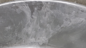 | ● The first metal liquid that enters the mold cavity forms an extremely thin and incomplete metal layer, which is then filled by the subsequent metal liquid and leaves a mark ● The casting surface shows a smooth texture that is consistent with the flow direction of the molten metal ● It can be felt by hand and has local sunken texture ● This defect has no tendency to develop and can be removed by polishing | 1) The cross-sectional area of the inner gate is too small and the position is improper, causing metal flow to fill the cavity asynchronously or splash and leave marks 2) Low mold temperature, such as zinc mold temperature below 150°C, aluminum mold temperature below 180°C, are prone to such defects 3) Too high filling speed 4) Too much paint is used 5) Insufficient pressure on the metal liquid | 1) Apply black oil to the hot mold to see the flow direction and filling order of the metal flow. Adjust the cross-sectional area, position or filling direction of the gate to achieve the purpose of synchronous filling 2) Use a mold temperature measuring gun to measure the mold temperature. Adjust the mold temperature to within the process requirements 3) On the casting surface, the metal flow at the gate will appear particularly bright. Appropriately adjust the filling speed to change the flow state of the metal liquid filling the cavity 4) The casting surface is black, and paint accumulation will occur locally. Adjust the paint concentration, and use the paint thinly and evenly 5) The opposite side of the gate on the casting surface is prone to failure to be pressed, accompanied by darkening of the surface. Appropriately adjust the injection pressure core structure force |
| 3 | Cold shut | 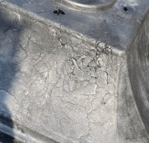 | ● The gaps formed when the metal flows with lower temperature butt each other but are not mixed ● Present irregular lines, with two types: penetrating and non-penetrating ● There is a tendency to develop under the action of external forces | 1) Low pouring temperature of the liquid metal, or low temperature of the mold 2) Alloy composition does not comply with the standard, poor fluidity 3) Liquid metal filling in separate strands, poor mixing 4) Irrational gate, too long flow 5) Low filling speed, or poor venting 6) Low specific pressure | 1) Blackening of the casting with flow marks: Increase the pouring temperature and mold temperature appropriately 2) Change the alloy composition to improve the fluidity 3) The cold shut caused by the collision of metal liquid is generally vortex-shaped with flow marks. Improve the pouring system and the filling direction of the inner gate. In addition, a slag bag can be opened on the edge of the casting to improve the filling conditions 4) The far end is not pressed solidly. Change the gate position and cross-sectional area, improve the overflow conditions, and increase the overflow volume 5) Blackening, often accompanied with surface air bubbles: Increase the injection speed 6) Overall casting looseness: improve the specific pressure |
| 4 | Short fills | 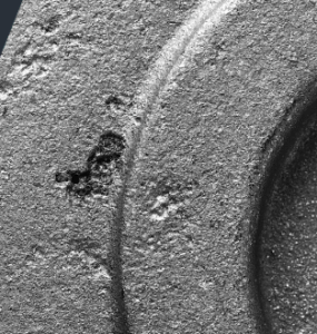 | Underfilled, poorly contoured, with missing edges and corners | 1. Poor alloy liquid flow: 1) The metal liquid contains a high amount of gas and is severely oxidized, resulting in decreased fluidity 2) Alloy casting and mold temperature is too low 3) Low velocity of inner gate 4) Insufficient oxygen pressure in the accumulator 5) Low filling degree of the pressure chamber, low specific pressure 6) Improper design such as too thin casting wall or large wall thickness difference 2. Poor runner system: 1) Improper gate location, diversion method, inner gate diversion, and sub runner design 2) Inner gate cross section too small 3. Poor venting conditions: 1) Poor venting 2) Spraying too much mold release agent, not blown dry 3) High mold temperature, high pressure of gas in the cavity, which make it difficult to exhaust | 1. Improve the fluidity of the alloy liquid: 1) The internal quality of the casting is poor, and there are many bubbles on the surface: Refine the alloy liquid and remove gas and non-metallic inclusions as much as possible 2) Accompanied by cold shut and flow marks: Appropriately increase the alloy pouring temperature and mold temperature 3) Small pits appear on the casting surface, and there is a cold shut around the undercast: Appropriately increase the injection speed 4) The pressure gauge has a buffer phenomenon and the displayed value does not meet the process requirements, and the casting is accompanied by the phenomenon of underpressure: Supplement nitrogen to increase the effective pressure (5) There are cold metal marks on the casting surface, and there is also the phenomenon of underpressure: Adjust the pressure chamber diameter, increase the injection pressure ratio, and use quantitative pouring (6) There is an obvious cold shut or underpressure around the undercast in the thin wall: Improve the casting structure, adjust the wall thickness appropriately, and open an auxiliary gate 2. Improve the gate system: 1) The front end of the undercasting is accompanied by cold shut and incomplete mixing: Select the gate position, diversion method and number of gate strands according to the filling simulation 2) It is often accompanied by sticky gate: Increase the cross-sectional area of the inner gate or increase the injection speed 3. Improve the exhaust conditions: 1) The color around the undercasting is black, accompanied by impurity accumulation and bubbles: Add overflow grooves and exhaust channels, and the deep cavity can be vented by the ejector gap or core gap 2) The surface color is not bright and the flow marks are serious: Use the release agent thinly and evenly, and close the mold after drying 3) It is often accompanied by sticky mold, severe tearing, and surface bubbles: Reduce the mold temperature to the specified range of the process |
| 5 | Blisters | 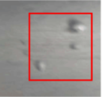 | ● Blisters formed by the expansion of accumulated gas under the surface of the casting sometimes burst ● There are two types: penetrating and non-penetrating. | 1) The mold temperature is too high and the mold is opened too early 2) The filling speed is too high, and the metal flow is involved in too much gas 3) The gas in the cavity is not discharged, and the exhaust is not smooth 4) The alloy melting temperature is too high 5) The aluminum alloy liquid is not completely degassed, and it absorbs more gas. When the casting solidifies, it precipitates and remains in the casting 6) Prime flow is generated during filling | 1) Lower the mold temperature and increase the holding time 2) Reduce the injection speed, appropriately increase the thickness of the gate to avoid vortex gas entrainment 3) Clean and add overflow grooves and exhaust channels 4) The metal flow pressed into the gate on the surface of the casting is particularly bright and accompanied by adhesion: reduce the temperature of the aluminum liquid 5) Detect the nitrogen content of the aluminum liquid, re-degas and refine the aluminum liquid 6) Open or increase the slag collection bag at the corresponding part, and adjust the flow direction of the gate |
| 6 | Cracks | 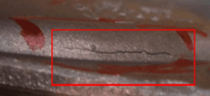 | ● The casting is destroyed or broken to form filamentary cracks ● there are of two types: penetrating and non-penetrating, and have a tendency to develop ● Cracks can be divided into cold cracks and hot cracks ● The metal at the crack of cold crack castings is not oxidized, while the metal at the crack of hot crack castings is oxidized | 1) The casting structure is unreasonable, the shrinkage is hindered, and the casting radius is too small 2) The core pulling and ejection devices are deflected during operation, and the force is uneven 3) The mold temperature, especially the core temperature, is low 4) The mold opening and core pulling time is too late 5) Improper alloy selection or excessive harmful impurities reduce the plasticity of the alloy 6) The casting structure has a particularly thick wall thickness difference, and the hot node is prone to cracks 7) The mold is pulled to produce a clamping force that causes cracking during ejection | 1) Improve the casting structure, reduce the wall thickness difference, and increase the casting radius 2) Correct the mold structure to ensure smooth ejection and demolding 3) Increase the mold working temperature 4) Shorten the mold opening and core pulling time 5) Strictly control harmful impurities and adjust the alloy composition 6) Optimize the casting wall thickness drop structure, increase point cooling, and eliminate heat knots 7) Increase the demolding slope to ensure smooth demolding |
| 7 | Porosity | 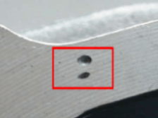 | The gas in the pressure chamber, runner and cavity is drawn into the interior of the die casting to form holes with relatively regular shapes and smooth surfaces | Premarily caused by entrained gas: 1) Improper selection of gate position and diversion angle, resulting in frontal impact and vortex of molten metal entering the cavity 2) Poor design of runner shape 3) Insufficient filling of the pressure chamber 4) Too high speed of the inner gate, resulting in turbulence 5) Poor exhaust 6) The position of the mold cavity is too deep 7) The furnace material is not clean and the refining is poor 8) The machining allowance is too large 9) Unreasonable die casting process, such as low specific pressure | 1) Select the gate position and diversion angle that are conducive to the removal of gas in the cavity to avoid the metal liquid closing the overflow system on the parting surface first 2) The nozzle cross-sectional area of the straight runner should be as large as possible than the cross-sectional area of the inner gate 3) Improve the filling degree of the pressure chamber, choose a smaller pressure chamber as much as possible and use quantitative pouring 4) Under the condition of good molding, increase the thickness of the inner gate to reduce the filling speed 5) Open an overflow groove at the last filling part of the cavity, and avoid the overflow groove and the exhaust channel being closed by the metal liquid 6) Open an exhaust plug in the deep cavity and use the gap to increase the exhaust 7) Furnace material must be treated clean, dry, strict compliance with the melting process 8) Reduce the machining allowance 9) Adjust the injection speed and the fast injection speed conversion point, reduce the pouring temperature, and increase the specific pressure |
| 8 | Stretch | 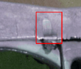 | ● Along the demolding direction, due to metal adhesion, the mold manufacturing slope is too small, resulting in scratches on the casting surface ● In severe cases, it becomes a scratched surface or even cracks | 1) The casting slope of the core and mold wall is too small or there is an inverted slope 2) There are indentations on the core and mold wall 3) The alloy adheres to the mold 4) The casting is tilted when it is ejected, or the axis of the core is tilted 5) The surface of the mold wall is rough 6) The paint is often not sprayed 7) The iron content in the aluminum alloy is less than 0.6% 8) The alloy pouring temperature is high or the mold temperature is too high 9) The pouring system is incorrect, directly impacting the mold wall or core 10) The filling speed is too high 11) The surface of the cavity is not nitrided | 1) Castings generally have bright marks and no fuzz: correct the mold to ensure the manufacturing slope 2) Pulling or even cracking occurs: polish the indentation, replace the core or weld the mold wall 3) Pulling and fuzzing: polish the mold 4) Large-area pull on one side, abnormal sound when ejecting: correct the mold structure 5) The pull is in the form of thin strips, multiple strips: grind and polish the surface 6) The mold surface is overheated and aluminum is evenly adhered: the amount of paint is thin and even, and the paint cannot be sprayed without leakage 7) Aluminum alloy adheres to the surface of the cavity: appropriately increase the iron content to 0.6~0.8% 8) Aluminum alloy adheres to the surface of the cavity, especially near the inner gate: reduce the pouring temperature and control the mold temperature within the process requirements 9) Severe aluminum adhesion to the mold wall or core: adjust the position and filling direction of the inner gate 10) Severe scouring at the gate of the mold cavity, accompanied by adhesion of aluminum alloy: appropriately reduce the speed 11) Aluminum alloy often adheres to the surface of the cavity: surface nitriding treatment is required |
| 9 | Depression | 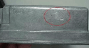 | The concave part that appears on the smooth surface of the casting is in a naturally cooled state | 1) Unreasonable casting structure design, too large wall thickness difference, local thick parts, resulting in heat nodes 2) Large alloy shrinkage 3) The cross-sectional area of the inner gate is too small and the position is improper 4) Low injection ratio 5) The local temperature of the mold is too high 6) Caused by damage and cracking of the die casting mold 7) Caused by holding in air, when the molten metal is filled, the local gas is not discharged and is compressed between the cavity surface and the molten metal surface to form | 1) Improve the structure of the casting to make the wall thickness uniform. The joints with large thickness differences should be gradually eased to eliminate heat nodes 2) Select alloys with small shrinkage and refine the alloy liquid 3) Correctly set the alloy pouring position and appropriately increase the cross-sectional area of the inner gate 4) Increase the injection force 5) Appropriately adjust the thermal balance conditions of the mold, use temperature control devices and point cooling, etc., spray the area for a longer time, and force cooling 6) Check whether the corresponding parts of the mold are damaged, protruding, and cracked: Repair the mold 7) Improve the exhaust conditions, the second-stage injection position is later, the first-stage injection speed is appropriately reduced, and the second-stage injection speed is appropriately reduced |
| 10 | Mesh-like marks | 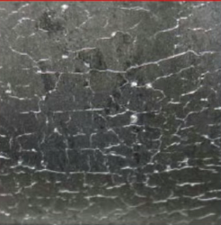 | Mesh-like raised marks and metal spurs on the surface of the casting formed as a result of thermal fatigue on the surface of the mold cavity | 1) Mold cavity surface cracks caused by marks of the inner gate area near the most concentrated heat conduction, frictional resistance, the strongest molten metal erosion, hot and cold alternation is the most dramatic, the most likely to produce stress concentration, resulting in thermal cracking, the formation of cracks 2) Improper mold material or incorrect heat treatment process 3) The temperature difference between hot and cold of the mold is big 4) The pouring temperature of alloy liquid is too high, and the preheating of the mold is not enough 5) Mold cavity surface roughness Ra is too large 6) Metal flow rate is too high and positive scouring of the wall 7) Die-casting mold wall is thin or have sharp corners 8) Mold cavity surface local after welding, and did not eliminate welding stress in time | 1) Use the mold according to the provisions of mold use and maintenance, and carry out stress relieving treatment in time. The parts that are prone to fatigue cracking should be cooled by additional points or adopt block structure. The production process should pay attention to the part of the spray, strengthen the forced cooling 2) Choose correct mold materials and reasonable heat treatment process 3) Through the simulation of temperature field analysis, to find out the cavity temperature imbalance. Set point cooling or point heating structure to ensure that the cavity temperature balance. The production process also needs to spray coating method to achieve temperature balance 4) As far as possible to reduce the alloy pouring temperature. Mold before die casting must preheat to working temperature range 5) Use roughness detector to detect the cavity surface roughness. Polish mold cavity surface to the required range, Ra value does not exceed 0. 2 6) High-speed region of the mold surface is easy to produce concave damage. Under the condition of good molding, reasonably reduce the filling speed of metal liquid. Change its filling direction 7) The surface of the casting at the thin wall is obviously bright. Repair the mold structure 8) Verify the mold production mold times, the weld patch should be very early, producing cracks. Should be according to the correct mold welding process welding mold. |
| 11 | Deformation | 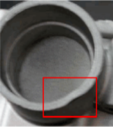 | The overall or local deformation of the casting’s geometry does not conform to the design requirements | 1) Poor structural design of castings, causing uneven shrinkage 2) Opening the mold too early, the rigidity of the casting is not enough 3) The casting slope is too small, and the mold force is large 4) Improper operation of removing the casting 5) Improper arrangement of the push rod position, ejection deviation 6) Unreasonable stacking of the produced castings 7) Unreasonable way to remove the gate, especially the gate layout is a curved structure 8) Local damage to the mold cavity, severe strain causing local deformation 9) Poor demoulding of the paint, sticking to the mold causing deformation 10) Uneven spraying of the paint causes inconsistent demoulding and deformation 11) The temperature difference between different parts of the cavity is large, causing inconsistent demoulding or local sticking to the mold 12) Subsequent treatment such as shot peening 13) Unreasonable transportation and packaging methods | 1) The casting can be obviously deformed after being placed out of the mold for a period of time: improve the structure of the casting to make the wall thickness uniform 2) The thick part of the casting is concave and the material may be squeezed: appropriately increase the holding time and strengthen the rigidity of the casting 3) The surface with too small casting slope has marks of brightening and strain: increase the casting slope when possible 4) There are marks of bumps on the surface: be careful when taking and placing the casting, and do not allow the casting body to be hooked when taking out the casting from the cavity 5) After opening the mold, manually eject it to check whether one end of the casting is ejected first: increase or reduce the local ejector accordingly to ensure balanced ejection 6) The stacking of castings should use special station equipment and cardboard separation protection 7) For easily deformed castings, the pouring method is used. The direction must be paid attention to. The best method is to use a punching die 8) The mold surface is damaged, and the corresponding part of the casting is scratched and fluffed: repair the mold 9) The corners of the casting or the core are seriously sticky with aluminum: replace the release agent 10) Sticking to the mold, and there is an abnormal sound when ejecting and demolding: spray release agent evenly 11) Partial sticking of the casting: Use a mold temperature gun to check the mold cavity temperature, add local point cooling or increase the spraying amount locally for forced cooling, and ensure that the overall temperature of the mold cavity tends to balance 12) Judge by dimensional detection before and after shot peening: Use a reasonable shot peening process, such as speed, time, etc. Use a stable hanging method, and use a special clamp when necessary 13) The casting is squeezed. Use high-strength outer packaging, and separate and protect each piece. Use box trucks as much as possible for transportation |
| 12 | Stick mold | 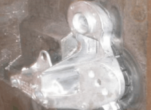 | Metal adhesion to die casting surface | 1) The temperature of the molten metal is too high 2) The temperature of the die casting mold is too high or too high 3) The iron content in (aluminum alloy) is too low 4) Improper use of mold release agent 5) There is a hot spot in the die casting mold 6) The temperature of the die casting mold or the molten metal is high 7) The casting or runner is not solidified | 1) Maintain the correct pouring temperature 2) Maintain the correct die casting mold temperature 3) Increase the iron content to 1.0% 4) Use the release agent correctly 5) Check whether the cooling water is smooth or increase the cooling speed 6) Ensure the correct mold temperature and metal liquid temperature 7) Increase the die casting cooling speed |
5.7 Notes
I. High-demand parts (such as automotive structural parts)
● Process audit:
– Perform VDA6.3 process audit
● Full report:
– Submit PPAP documents, including 100% measurement data
II. Low-cost parts (such as daily necessities)
● Simplified control:
– The sampling frequency can be reduced to 2%, but key functional dimensions still need 100% inspection
– Minor surface defects are allowed (such as pores with a diameter of ≤0.5mm)
6. Advantages and Disadvantages of Aluminum Die Casting
Compared with other basic aluminum casting methods, aluminum die casting offers significant advantages in efficiency, consistency, and surface quality for mass-produced cast aluminum parts.
6.1 Advantages
1) High efficiency
● The die-casting process has a high degree of automation, a short production cycle, is suitable for mass production, and has relatively low costs
2) High precision and complex molding
● It can manufacture parts with complex shapes, thin walls (up to 0.5mm), and fine details (such as gears, housings, etc.), reducing the need for subsequent processing
3) Excellent surface quality
● The surface finish of die-casting parts is high, and surface treatments such as electroplating and spraying can be directly performed
4) Good material properties
● Aluminum alloy is lightweight (density of about 2.7g/cm³), and has good strength, thermal conductivity and corrosion resistance
5) High consistency
● The mold life is long (up to hundreds of thousands of times), the product has good dimensional stability, and is suitable for standardized production
6) Reduce machining steps
● Compared with other processes (such as sand casting), die castings usually do not require a lot of machining, saving time and materials
6.2 Disadvantages
1) High initial cost
● Mold design and manufacturing are complex, with large initial investment, suitable for large-scale production, and poor economic efficiency for low-volume orders
2) Material restrictions
● Only applicable to low-melting-point metals such as aluminum and zinc alloys, not applicable to high-melting-point metals (such as steel and iron)
3) Risk of internal defects
● Rapid cooling is prone to produce pores and shrinkage holes, which may affect the mechanical properties of parts (such as fatigue resistance)
4) Size restrictions
● Due to equipment tonnage and mold restrictions, it is usually used for small and medium-sized parts (generally weighing <10kg), and it is difficult to achieve oversized parts
5) Post-treatment requirements
● Porosity may require subsequent heat treatment or infiltration treatment, which increases costs
6) Low design flexibility
● Once the mold is built, the modification cost is high and it is difficult to change the product structure
7. Considerations During Part Design
Proper part design is critical in aluminum die casting, as design decisions directly affect defect risks, tooling cost, and the final quality of cast aluminum components. While many principles also apply to basic aluminum casting, die casting places stricter requirements on wall thickness, draft angles, and flow behavior.
7.1 Wall Thickness
● Uniformity: Try to keep the wall thickness uniform (recommended 2.5~4mm), avoid local excessive thickness (easy shrinkage) or excessive thinness (difficult to fill)
● Minimum wall thickness: Usually ≥0.5mm (depending on the fluidity of the alloy), too thin may cause cold shut or insufficient filling
● Transition: Use gradual transition (such as fillet or slope) at the junction of thick and thin to reduce stress concentration
7.2 Draft Angle
● Necessity: Facilitate demolding, reduce mold wear and part scratches
● Typical values:
– External surface: 0.5° – 1.5°
– Internal surface: 1° – 2° (due to greater shrinkage and tightening force)
● Special requirements: The textured surface needs to increase the slope (add 1° for every 0.025mm texture depth)
7.3 Rounded Corners
● Avoid sharp corners: Design rounded corners (R≥0.5mm) at all edges and corners to reduce stress concentration and improve metal liquid flow
● Internal rounded corners: Especially important, it can reduce the risk of cracks and extend the life of the mold
7.4 Rib and Support Structure
● Rib design:
– Thickness ≤ 60%~80% of the main wall thickness, height ≤ 5 times the wall thickness
– Avoid cross ribs and adopt staggered layout to reduce thick areas
● Functional integration: Replace welding or assembly parts with ribs, bosses and other structures to simplify the process
7.5 Hole and Slot
● Direct die-casting hole:
– Minimum hole diameter ≥1.5mm (depth-to-diameter ratio ≤8:1), avoid small deep holes (need post-treatment)
– Leave enough draft angle at the bottom of the blind hole
● Slots and grooves: Width ≥2mm, depth ≤3 times the width, avoid mold sliders that are too complicated
7.6 Parting Line and Flash
● Parting Line Position: Try to design it in non-appearance surface or low-precision area
● Flash Control: Avoid fine structures (such as threads) near the parting line, and flash needs to be removed later
7.7 Tolerance and Surface Quality
● Dimension tolerance:
– General tolerance ±0.1 – 0.3mm (depending on size and mold grade)
– High-precision areas need to reserve machining allowance (such as bearing seats)
● Surface roughness: Usually Ra 1.6- 6.3μm, which can be further improved by polishing or sandblasting
7.8 Material Selection
● Common alloys:
– ADC12: high silicon, good fluidity, suitable for thin-walled parts
– A380: balanced strength and fluidity
– Al-Mg series: corrosion resistant, but poor fluidity
● Shrinkage rate: The shrinkage rate of aluminum alloy is about 0.4%~0.7%, which needs to be compensated during design
7.9 Mold Complexity and Cost
● Simplify mold structure:
– Reduce lateral core pulling (sliders) and movable inserts to reduce mold costs
– Avoid undercut structures (or design as post-treatment features)
● Number of mold cavities: Balance mold size and production efficiency according to production requirements
7.10 Post-Treatment Requirements
● Machining allowance: Reserve 0.5- 2mm allowance for surfaces that need to be machined (such as sealing surfaces and threaded holes)
● Porosity treatment: Pressure-bearing parts may require impregnation (filling micropores with sealants) or hot isostatic pressing (HIP)
7.11 Simulation Verification
● Flow analysis: Use software (such as MAGMA, Flow-3D) to simulate the filling process and optimize the gating system and exhaust
● Defect prediction: Identify risks such as shrinkage and cold shut in advance and adjust the design or process parameters
7.12 Notes
– Avoid locally thick sections (such as solid blocks)
– Avoid sharp thickness changes
– Avoid deep cavities or closed structures without exhaust paths
7.13 Case Study
● Auto parts: The gearbox housing adopts uniform wall thickness + reinforcement ribs, and the parting line is set on the non-matching surface
● Electronic housing: The heat sink fins are designed with thin walls (1mm), a draft angle of 2°, and a rounded corner at the root
8. Alternatives to Aluminum Die Casting
Although aluminum die casting is ideal for high-volume production, it is not the only option for producing cast aluminum parts. Depending on batch size, complexity, and performance requirements, various basic aluminum casting and alternative manufacturing processes may be more suitable.
8.1 Sand Casting
● Features: Sand mold molding, suitable for large parts and complex shapes
● Advantages:
– Low cost: simple mold, suitable for low-volume orders
– Can produce super large parts: weight up to several tons
– Wide selection of materials: including high melting point aluminum alloys
● Disadvantages:
– Rough surface (Ra 12.5 – 25μm), requiring a lot of post-treatment
– Low dimensional accuracy (tolerance ±1 ~ 3mm)
● Application: engine block, large structural parts
8.2 Metal Mold Casting (Gravity/Low-Pressure Casting)
● Gravity casting: The molten metal fills the metal mold by gravity
– Advantages: dense structure, few pores, suitable for medium volume order
– Disadvantages: slow cooling, lower productivity than die casting
● Low-pressure casting: The molten metal is injected into the mold by air pressure
– Advantages: stable filling, suitable for high-quality parts (such as wheels)
– Disadvantages: high equipment cost
● Common disadvantages: mold cost is still high, and complex structures are limited
8.3 Investment Casting (Lost Wax Casting)
● Features: Use wax mold to make ceramic shell, and pour after melting wax
● Advantages:
– Ultra-high precision (tolerance ±0.1mm), smooth surface (Ra 1.6~3.2μm)
– Can cast extremely complex parts (such as turbine blades)
● Disadvantages:
– High cost, long cycle, suitable for low-volume orders of high-value-added parts
– Applications: Precision parts for aerospace, medical devices
8.4 Squeeze Casting (Liquid Die Forging)
● Features: The molten metal solidifies under high pressure, combining the advantages of casting and forging
● Advantages:
– Dense structure (mechanical properties close to forgings)
– Extremely low porosity, can be strengthened by heat treatment
● Disadvantages:
– Expensive equipment, shape complexity is lower than die casting
– Application: High-strength structural parts (such as suspension parts)
8.5 Semi-Solid Metals (SSM)
● Features: Pressing semi-solid metal slurry into the mold
● Advantages:
– Reduce shrinkage and improve mechanical properties (strength increased by more than 20%)
– Can produce thin-walled parts (1 – 2mm)
● Disadvantages:
– Complex process control and high raw material cost
● Application: High-safety automotive parts (such as steering knuckles)
8.6 Machining (CNC)
● Features: Cut directly from aluminum blank
● Advantages:
– No mold cost, suitable for prototypes or low-volume orders
– Ultra-high precision (±0.01mm), high design freedom
● Disadvantages:
– Material waste is high, and costs rise sharply with order quantity increases
– Applications: High-precision fixtures, aerospace components
8.7 Additive Manufacturing (3D Printing)
● Process types: SLM (Selective Laser Melting), DMLS (Direct Metal Laser Sintering)
● Advantages:
– No molds are required, and complex cavities/topology optimization structures can be manufactured
– Fast iteration, suitable for personalized customization
● Disadvantages:
– High cost (materials, equipment), rough surface (post-treatment required)
– Anisotropic mechanical properties
● Applications: Lightweight heat sinks, customized implants
8.8 Stamping + Welding (Sheet Metal Process)
● Features: Aluminum sheet is stamped and then welded for assembly
● Advantages:
– Low cost, suitable for thin-walled shells (such as electronic housings)
– Fast production
● Disadvantages:
– Limited structural complexity, lower strength than integral castings
8.9 Forging (Hot Forging/Cold Forging)
● Features: high-density structure obtained through plastic deformation
● Advantages:
– Best mechanical properties (fatigue strength, toughness)
– No pore defects
● Disadvantages:
– Simple shape, requires subsequent machining
– Application: load-bearing parts (such as connecting rods, aviation joints)
8.10 Alternative Process Selection Guide
| Table 4 – Alternatives to Aluminum Die Casting | |
| Requirements | Alternatives |
| Low volume order, low cost | ● Sand casting ● Sheet metal |
| High-precision, complex parts | ● Investment casting ● Machining |
| High strength, fatigue resistance | ● Squeeze casting ● Forging |
| Lightweight thin wall | ● Semi-solid metal ● Die casting |
| Rapid prototyping/complex structures | ● 3D printing |
| Extra large size | ● Sand casting |
8.11 Key Factors
● Batch: Die casting is suitable for large volume orders, and sand casting/machining is suitable for small volume orders
● Performance requirements: Forging or extrusion casting is ideal for high-load-bearing parts
● Complexity: Investment casting or 3D printing is a good choice for complex cavities
● Cost: Balance mold costs with unit costs (such as sheet metal replacing simple shells)
9. Conclusion
Aluminum die casting is a proven and efficient solution for manufacturing high-quality cast aluminum parts with complex geometry and tight tolerances.
As an advanced form of basic aluminum casting, it is particularly suitable for large-volume production where consistency, automation, and long-term cost efficiency are critical.
Xiamen Eternal Precision evaluates each project based on design, application, and budget to determine whether die casting or other aluminum casting methods deliver the best overall value.