1. What Is a Mold for an Injection Molding Machine
A mold for injection molding machine is the component that truly defines the result of the process. The same injection molding machine can produce stable, high-quality parts or problematic, inconsistent ones purely based on the mold being used. The mold controls how the plastic flows, cools, and solidifies, making it the primary factor behind part geometry, dimensional stability, surface finish, unit cost, and mass-production feasibility.
In real production, the machine provides force and heat, but the mold determines whether a design can be manufactured reliably at scale.
2. How an Injection Mold Works Inside the Machine
Clamping
The mold closes and locks inside the machine. If the two halves do not seal perfectly, plastic escapes at the parting line. This causes flash and size variation. This is a mold fit problem, not a machine issue.
Injection
Molten plastic enters through the sprue, flows along the runner, and passes the gate into the cavity. A poor flow path leads to short shots, weld lines, and weak internal structure. The machine pushes plastic in, but the mold decides how it flows.
Cooling
Plastic solidifies inside the mold. Cooling channel layout determines most of the cycle time. Uneven cooling causes warpage and unstable dimensions, even with the same machine settings.
Opening and Ejection
The mold opens and ejector pins push the part out. Insufficient draft, bad pin placement, or poor venting causes sticking, drag marks, and white stress lines. These defects appear at ejection, but they originate from mold design.
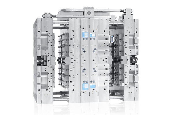
3. Core Components of an Injection Mold
Forming System
This system defines the part shape. The core and cavity form the plastic, but the parting line decides cost. Poor parting line design increases machining complexity, flash risk, and polishing time. Every extra adjustment here adds tooling cost and long-term maintenance work.
Feeding System
This system controls how plastic enters the mold. Cold runners increase material waste but keep tooling simple. Hot runners reduce scrap but raise tooling cost and maintenance risk. Gate type directly affects surface appearance and local strength. A bad gate choice often shows up later as cosmetic complaints or cracked parts.
Cooling System
This system decides productivity. Cooling usually takes around 60% of the total cycle time. Inefficient or uneven cooling causes warpage, sink marks, and shot-to-shot size variation. Extending cooling time can hide the problem, but it increases unit cost and reduces output.
Ejection & Venting System
This system determines whether parts come out cleanly. Poor ejector pin placement causes drag marks, deformation, or broken parts. Inadequate venting traps air, leading to burn marks and surface defects. These issues appear at demolding, but customers see them as quality failures.
4. Types of Injection Molds
Mold type selection often depends on production volume, part geometry, and the type of plastic material being processed. Different molds solve different problems, but choosing the wrong type usually increases cost, lead time, or long-term risk.
4.1 Low-Volume or Prototype Projects
Aluminum molds and rapid tooling are commonly used for early-stage projects. They are faster to build and lower in upfront cost, making them suitable for validation and short runs. The risk is durability and dimensional stability. When pushed into higher volumes, these molds wear quickly and often create inconsistent parts.
4.2 Standard Production Molds
For stable production, two-plate and three-plate molds are the most common choices. The real difference is not the number of plates, but how the gate is handled and how easy the mold is to maintain. Poor gate separation or difficult access increases downtime and maintenance cost over time.
4.3 Complex Geometry or Undercuts
Parts with undercuts or side features require sliders, lifters, or side-action mechanisms. These molds solve geometry problems but significantly increase tooling complexity. Every moving component adds cost, extends lead time, and raises the risk of mechanical failure during production.
4.4 High-Volume Production
Multi-cavity, stack molds, and hot runner systems are used to maximize output. More cavities increase productivity, but only if filling, cooling, and ejection remain balanced. Pushing cavity count too high often leads to uneven quality, longer tuning time, and higher scrap rates. More cavities are not always more efficient.
5. Mold Materials & Plastic Material Compatibility
5.1 Mold Materials: Chosen by Volume, Not by Price
Mold material should be selected based on expected production volume and the plastic being processed, not initial tooling price.
For less than 10k shots, aluminum molds or soft tooling are often sufficient. They are fast and inexpensive upfront, but wear quickly. As tolerances drift, scrap rates increase even though the mold is not physically damaged.
For 10k–100k shots, pre-hardened steel molds are commonly used. They balance cost and durability, but require proper cooling and surface treatment. Poor material choice here often leads to rising defect rates after several months of production.
For 100k+ shots, hardened steel molds are the standard. They support long-term dimensional stability and consistent surface quality. Cheaper tooling at this stage often looks attractive initially, but higher scrap, downtime, and maintenance costs quickly exceed the savings.
This is why some molds appear inexpensive at the start but become costly over time, and why some customers see increasing rejection rates even though the mold itself has not failed.
5.2 How Plastic Material Selection Affects Mold Design
Plastic material selection directly changes mold structure, cooling strategy, venting design, and tolerance control.
1) Material PP
When working with material PP, mold designers must carefully manage shrinkage and cooling uniformity. PP flows easily, but its high shrinkage rate makes parts sensitive to warpage and dimensional variation. Cooling layout and cycle balance are critical to maintain stable dimensions.
2) Material PC
Compared with material PP, material PC requires higher processing temperatures and higher injection pressure. This places greater demands on venting design, gate location, and mold steel selection. Poor venting often results in burn marks or surface defects rather than filling issues.
3) Nylon 6 6 and Nylon 6
For engineering applications using nylon 6 6 and nylon 6, moisture absorption is a key concern. Mold tolerances must account for dimensional change, and post-molding conditioning often becomes part of the production process. Ignoring moisture behavior leads to unstable part size even when the mold is built correctly.
4) Other Materials
Filled plastics, flame-retardant grades, and reinforced materials introduce additional wear, thermal stress, and surface finish challenges. These materials often require upgraded mold steels, optimized cooling, and stricter maintenance planning.
6. Design for Moldability: What Engineers Often Get Wrong
Uneven Wall Thickness
Uneven walls cool at different rates. If not corrected, parts will warp, sink, or drift out of tolerance even when machine settings remain unchanged.
Too Many Sharp Corners
Sharp internal corners concentrate stress and restrict material flow. If left unchanged, cracks, short shots, and premature part failure are likely during use.
Insufficient Draft Angle
Draft angle requirements may vary significantly between material PP, material PC, and nylon 6 6 and nylon 6 due to differences in stiffness and surface behavior. If draft is insufficient, parts stick to the mold, causing drag marks, white stress lines, and unstable ejection.
Ignoring Venting
Poor venting traps air during filling. If not addressed, burn marks, surface defects, and incomplete filling appear, often mistaken for material or machine issues.
Sacrificing Moldability for Appearance
Over-prioritizing sharp edges or cosmetic details often reduces process stability. If unchanged, scrap rates rise and production becomes inconsistent, even if early samples look acceptable.
7. Common Mold-Related Defects and Their Root Causes
Short Shot
Most short shots originate at the gate or runner. Restricted flow paths, undersized gates, or unbalanced runners prevent the cavity from filling completely. Increasing injection pressure may hide the issue temporarily, but the root cause remains mold-related.
Warpage
Warpage is primarily a cooling problem. Uneven cooling channels cause different shrinkage rates across the part. This is why parts molded with PP tend to warp more easily when cooling is not uniform, even if filling looks perfect.
Sink Marks
Sink marks point to poor cooling and wall thickness management. Thick sections cool slower and shrink after the surface has solidified. Extending cycle time reduces the symptom, but redesigning cooling and geometry addresses the cause.
Flash
Flash is almost always linked to the parting line. Poor alignment, wear, or insufficient mold stiffness allows molten plastic to escape. Machine clamp force cannot compensate for a badly designed or worn parting line.
Burn Marks
Burn marks are caused by trapped air and inadequate venting. High-temperature materials such as PC are more prone to this issue because compressed air ignites under heat. Improving vent placement solves the problem faster than adjusting process settings.
8. Mold Cost, Lead Time, and Lifetime: What Buyers Should Really Ask
Why Mold Quotes Vary So Much
Mold pricing differences rarely come from profit margins alone. They usually reflect choices in mold steel, cooling design, cavity balance, and expected service life. A lower quote often means simplified cooling, looser tolerances, or reduced durability. These savings show up later as higher scrap rates and longer tuning time.
Where Lead Time Is Commonly Underestimated
Lead time is not just machining. Design review, DFM revisions, steel procurement, heat treatment, and mold testing often take longer than expected. Projects fall behind when these steps are rushed or skipped, even if machining finishes on time.
Mold Lifetime Is Not Just Shot Count
A mold may still run after hundreds of thousands of shots, but that does not mean it produces acceptable parts. Wear in gates, runners, cooling channels, and parting lines gradually reduces dimensional stability and surface quality. Functional life matters more than theoretical shot life.
The Hidden Cost of Poor Maintenance
Inadequate cleaning, lubrication, and inspection accelerate wear. Venting clogs, cooling efficiency drops, and ejector systems become unstable. These issues increase downtime and scrap long before the mold is considered “worn out.”
Buyers who ask these questions early focus on long-term production stability, not just upfront tooling cost. That mindset separates reliable production partners from short-term suppliers.
9. How to Choose the Right Mold for Your Injection Molding Machine
Choosing the right mold for injection molding machine requires not only understanding mold structures, but also how production goals and material behavior interact with tooling design. Use the checklist below to make a decision that holds up in real production.
- Production Volume
Match the mold build to expected output, not to the first order. Underspecified molds become unstable as volume increases.
- Plastic Material
Different materials place different demands on cooling, venting, tolerances, and steel selection. Material choice should influence mold design from the start.
- Dimensional and Cosmetic Requirements
Tight tolerances and high surface expectations increase tooling complexity and maintenance needs. Decide early what truly matters.
- Budget vs. Long-Term Cost
Lower tooling cost often trades off stability, cycle time, or lifespan. Evaluate total production cost, not just the mold price.
- Future Upgrades
Consider whether cavity count, runner system, or automation may need to scale later. Some molds can evolve; others cannot.
When these factors are evaluated together, mold selection becomes a controlled engineering decision rather than a pricing compromise. That is how consistent quality and predictable production are achieved.
10. FAQ
1) What is the difference between an injection mold and an injection molding machine?
An injection molding machine provides clamping force, heat, and injection pressure. The injection mold defines the part shape, cooling behavior, surface quality, and dimensional stability. The machine runs the process; the mold determines the result.
2) How long does an injection mold last?
Lifetime depends on mold steel, maintenance, material abrasiveness, and process stability. A mold may continue running after many shots, but functional life ends when it can no longer hold dimensions or surface quality consistently.
3) Can one mold be used on different injection molding machines?
Yes, if clamp size, tie-bar spacing, shot size, and interface standards are compatible. However, moving a mold without revalidation often leads to filling or cooling imbalance.
4) What affects the cost of a mold most?
Cooling design, cavity count, parting line complexity, tolerance requirements, and expected service life. Lower quotes often simplify these areas, increasing long-term production cost.
5) Does material PP require a different mold design than material PC?
Yes. PP’s higher shrinkage demands tighter cooling control, while PC’s higher processing temperature requires better venting and more robust steel selection.
6) How does nylon 6 6 and nylon 6 affect mold tolerance?
Moisture absorption impacts dimensional stability. Mold tolerances and post-molding conditioning must be planned to maintain consistent part size.