
Gate: also known as the feed port, is the channel connecting the runner and the cavity, which affects the melt flow, molding quality and appearance
5.6.1 Common Injection Molding Gate Types & Features
| Gate Types | Pictures | Features | Applications | Advantages | Disadvantages |
|---|---|---|---|---|---|
| Edge Gate | 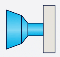
| ● Located at the edge of the parting line ● Rectangular or fan-shaped cross-section | ● Most common plastic parts: such as shells, boxes | ● Easy to process ● Widely applicable | ● Requires manual trimming ● May leave marks |
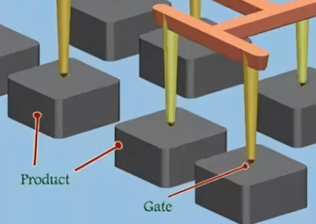
| Pin Gate | 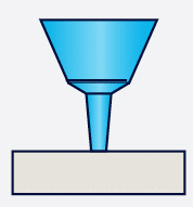
| ● Small diameter (0.5~1.5mm) ● Automatic cutting | ● Appearance parts: such as mobile phone cases, transparent parts | ● Automatic cutting ● Good appearance | ● Large pressure loss ● Three-plate mold required |
| Tunnel Gate/Submarine Gate | 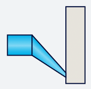
| ● Submarine obliquely under the parting line ● Automatically cut off when ejected | ● Internal hidden gate: such as home appliance parts | ● No post-treatment required | ● Complex design ● Prone to wear |
| Fan Gate | 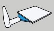
| ● Wide and thin fan-shaped cross section ● Uniform feeding | ● Flat parts: such as panels, thin-walled parts | ● Reduce flow stress | ● Large gate residue |
| Ring Gate | 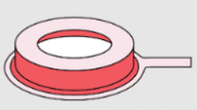
| ● Plastic is injected around the cylindrical part | ● Tubular parts: such as pen holders, bottle caps | ● No weld marks | ● Much waste ● Post-treatmentg required |
| Overlap Gate | 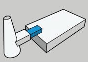
| ● The gate is located on the parting line ● Typically rectangular | ● Suitable for multi-cavity molds: small and medium-sized plastic parts | ● Easy to process ● Flexible selection of gate position ● Easy to remove gate | ● Venting difficulty ● High pressure loss |
| Sprue Gate | 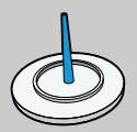
| ● The sprue supplies plastic directly to the part ● The sprue is attached to the part | ● Thick wall or high stress parts: such as handles | ● Good filling | ● Large residue ● Need to be trimmed |
| Cashewgate/Banana Gate | 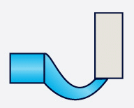
| ● From the runner to the part connection, it is curved like a banana | ● Products with high requirements for appearance quality and structural strength ● Like automotive parts, electronic product housings, household appliances, etc | ● Simple structure ● Small flow resistance ● Easy gate removal | ● Difficult to process ● Higher mold cost |
5.6.2 How to Select the Correct Gate Position/Location
I. Appearance (Gate Marks & Weld Lines)
Gate Marks:
● For appearance parts (such as mobile phone cases and transparent parts), pingates or submarine gates are preferred to reduce visible gate residues
● Avoid setting gates on high-gloss surfaces, otherwise shrinkage marks or uneven gloss are likely to occur
Weld Lines:
● Weld lines should avoid appearance surfaces or high-stress areas (such as buckles and threads)
● Move weld lines to non-critical areas (such as the back of ribs) by adjusting the gate position or increasing the number of gates
Optimization:
● Use fan gates or multi-point injection to make the melt fill evenly and reduce weld line strength issues
● CAE analysis (such as Moldflow) simulates the weld line position and optimizes the gate layout in advance
II. Part Function
Structural Strength:
● Gates should not be set in high-stress areas (such as assembly holes and buckles) to avoid fractures caused by weld lines
● Thick-walled areas are suitable for locating gates to help pressure maintenance and shrinkage compensation, also to reduce shrinkage holes
Assembly Impact:
● Avoid gates affecting mating surfaces or sealing surfaces (e.g., gates for waterproof parts should be away from joints)
Optimization :
● For gears, bearings and other load-bearing parts, use ring gates or multi-point injection to ensure uniform filling and avoid unilateral stress concentration
III. Mold Machining
Feasibility:
● The gate position should be convenient for mold machining, and avoid being set in deep cavities or narrow areas, which will cause processing difficulties
● The gate should be located on the parting line as much as possible to facilitate the cleaning of the gate during mold processing and use
● The three-plate mold (pin gate) is more complex in structure and more expensive than the two-plate mold (edge gate), check whether it is necessary
Mold Lifetime:
● The gate should not be directly opposite to the small core or slider, otherwise long-term injection will easily lead to erosion and wear
Optimization:
● Preferably choose standard gates (such as edge gates) to reduce the processing difficulty caused by special structures
● Avoid using pin gates for high-glass fiber materials (such as PA+GF) to prevent the gate from wearing too quickly
IV. Prevent Warping
Unbalanced Flow:
● Single-side gates can easily lead to asymmetric shrinkage and warping(e.g., long parts should be injected at both ends)
● Multi-point gates or fan gates are recommended for thin-walled parts to ensure uniform filling
Cooling Effect:
● Set the gate position near the cooling water channel to avoid deformation caused by partial overheating
Optimization:
● Symmetrical layout of gates (e.g., 4-point glue injection for box-type parts) to balance shrinkage stress
● Combined with mold temperature analysis, ensure uniform cooling of the gate area
V. Gate Removal
Automated Production:
● Submarine and point gates can be automatically cut off, which is suitable for unmanned production
● Edge and sprue gates need to be manually trimmed, which increases post-treatment costs.
Residue of Gate Removal:
● Gate design should consider the aesthetics, such as hiding the fracture surface of submarine gates as much as possible on the inside
Optimization:
● For appearance parts, automatic gate cutting design (such as three-plate mold point gate) is preferred
● For manually trimmed gates (such as edge gates), reserve trimming margin to avoid damage to the product
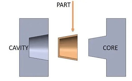
5.7 Ejection
Ejection: smoothly release the cooled and solidified plastic parts from the cavity or core
5.7.1 Common Ejector Systems and Their Applications
| Ejector Types | Pictures | Features | Applications | Advantages | Disadvantages |
|---|---|---|---|---|---|
| Pin Ejector | 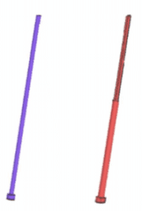
| ● Round/square ejector pin ● High degree of standardization | ● Most flat or simple curved plastic parts | ● Low cost ● Easy processing | ● Local stress concentration |
| Sleeve Ejector | 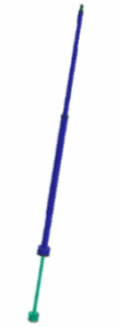
| ● Sleeve structure ● Inner core fixed ● Outer tube ejection | ● Deep cavity columnar structure (such as bottle mouth, BOSS column) | ● Stable demoulding of deep cavity | ● Complex machining |
| Air Ejection | ● Compressed air blows out plastic parts | ● Thin-walled deep-cavity parts: such as cup-shaped products | ● No ejection marks | ● Need air path system support | |
| Push Plate Ejection | 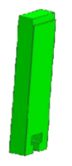
| ● The whole plate pushes the part to be released | ● Large flat thin-walled parts: such as box covers, trays | ● Uniform force | ● Complex mold structure |
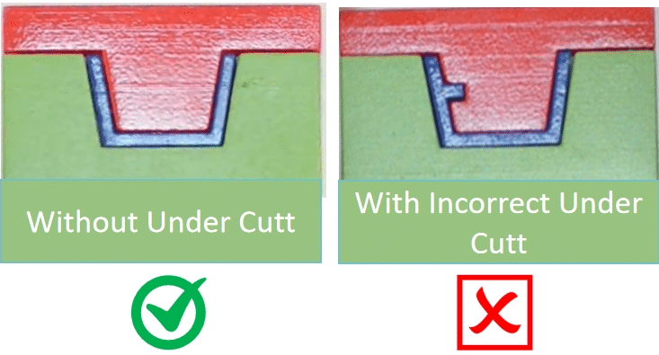
| Inclined Ejector | 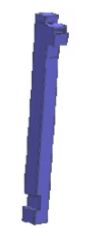
| ● Angle ejector block with core pulling function | ● Inner undercut structure: such as buckle, inner groove | ● No slider required | ● Risk of motion interference |
5.7.2 Ejector System Design
I. Ejector Balance
● Ejector pins/ejector blocks need to be laid out symmetrically to avoid product warping caused by unilateral force (e.g., rectangular parts need at least 4 ejection points)
● The ejector force point should be close to the area with the greatest demoulding resistance (e.g., BOSS column, bottom of deep rib)
II. Ejector Position Selection
● Eject at parts with high structural strength such as reinforcing ribs, bosses, thick-walled areas
● Avoid ejecting at the exterior surface or thin-walled area to prevent white ejection marks or cracking (e.g., transparent parts need to use air ejector or push plate)
III. Ejector Stroke Calculation
● Minimum stroke = part demoulding height + safety margin (typically +2~5mm)
● Deep cavity parts need to check the aspect ratio of the ejector pin (generally ≤10:1 to prevent bending)
IV. Matching Clearance Control
● Single-side clearance between ejector pin and hole:
General:
– Small diameter ejector: the single-side clearance is usually 0.005mm to 0.01mm for an ejector with a diameter of 2mm
– Larger diameter ejector: for an ejector with a diameter of more than 6mm, the single-side clearance can be increased to 0.015mm to compensate for the dimensional changes caused by thermal expansion
High-Precision Mold:
– For high-precision molds (such as optical or medical device molds), the single-side clearance needs to be reduced to within 0.003mm, and use nitriding or titanium plating to reduce the friction coefficient
V. Key Points
1) Anti-Stuck and Lubrication
● The ejector needs to be provided with a guide section (length ≥ 2 times the diameter), and the sleeve ejector needs to be equipped with a wear-resistant copper bushing
● High friction areas (such as inclined ejectors) should be designed with oil grooves or use self-lubricating materials (such as graphite copper)
2) Ejector Reset Safety
● A pre-reset mechanism (such as spring + micro switch) must be set to prevent the ejector from not returning when the mold is closed and causing collision
● The inclined ejector mechanism needs to verify the mold closing interference (through CAD motion simulation).
3) PartAdaptability
● Soft materials (such as TPU) need to increase the ejector contact area (using flat ejectors or ejector blocks) to reduce the risk of puncture
● The ejection speed of high-gloss parts needs to be controlled slowly and in sections (adjusted by the ejection program of the injection molding machine)
4) Venting and Cooling
● The ejector arrangement needs to avoid the cooling water channel, but it can also serve as an auxiliary venting channel (ejector gap venting)
● When ejecting a large area (such as a push plate), a heat dissipation slot needs to be added on the back of the ejector plate to prevent thermal deformation
5.8 Mold Lifetime
How to Increase Mold Lifespan
5.8.1 Mold Design
I. Optimize Structural Design:
● Design the mold structure to avoid stress concentration. For example:
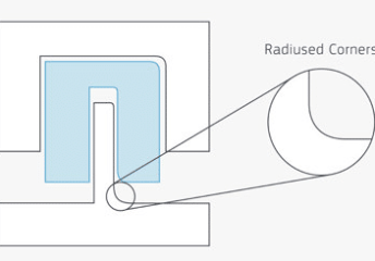
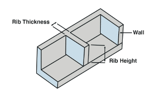
– At the corners and thin walls of the mold where stress concentration is likely to occur, use rounded corner transitions and add reinforcing ribs to improve the strength and stability
– For molds with complex structures, a block design can be used to facilitate processing and maintenance
II. Select Suitable Materials:
● Choose suitable mold materials according to the use requirements and working conditions. For example:
– For molds with high hardness and high wear resistance, select Cr12MoV and H13 etc
– For molds that require corrosion resistance, use stainless steel
III. Cooling System:
● Design reasonable cooling water channels to ensure uniform cooling of all parts of the mold to avoid deformation or cracking due to excessive temperature difference
● The diameter, length, spacing and other parameters of the cooling water channel should be optimized according to factors such as the size, shape and material of the mold
5.8.2 Machining
I. Improve MachiningAccuracy:
● Use advanced equipment and processes to improve the mold machining accuracy and surface quality
● For mold key parts, such as the cavity, core, parting surface, etc., fine processing and polishing should be carried out to reduce friction and wear
II. Heat Treatment:
● Perform appropriate heat treatment, to improve the mold hardness, strength, wear resistance and toughness
● Control heat treatment parameters according to the mold material and use requirements to ensure the heat treatment effect
5.8.3 Use and Maintenance
I. Process Parameters:
● Set process parameters based on mold material, structure and part features
● The clamping force should be moderate
● Adjust injection pressure and speed based on the part shape and size to avoid excessive pressure and speed from impacting the mold
● Control mold temperature within a suitable range to avoid overheating or overcooling
II. Regular Clean and Lubrication:
● After each production, clean mold (such as plastic residue, flash, burrs, etc.)to prevent these impurities from scratching or corroding the mold
● Lubricate and maintain regularly mold moving parts, such as ejector pins, guide pins, sliders, etc
● Use lubricants (such as high-temperature grease)to ensure the smooth operation of the moving parts and reduce wear
III. Inspection and Maintenance:
● Regularly check mold, including mold appearance and dimensions, etc. to promptly detect defects (such as wear, deformation, cracks, etc.)
● Some wearing parts(such as ejector pins, guide pins, sealing rings, etc.) should be replaced regularly to ensure the normal mold operation
6. Post-Treatment
Some molded parts require further treatment to improve their aesthetics, functionality, durability. There are a variety of surface treatment depending on the material, application and customer requirements.
6.1 Mechanical Treatment
6.1.1 Polishing
● Enhance gloss, often used for high-gloss mirror plastic parts
● Applications
– Transparent parts: PC/PMMA optical components
– High-gloss home appliance panels
6.1.2 Sandblasting
● Change the surface texture of the workpiece to improve mechanical properties and fatigue resistance
● Remove the sharp edges and burrs on the workpiece
● Applications
– Automotive interior parts
– Anti-slip pattern on tool handles
6.2 Chemical Treatment
Electroplating (Physical Vapor Deposition / Water Plating)
● Offer the plastic surface a metallic texture, improve the grade and conductivity
● Type:
– Physical Vapor Deposition (PVD): Suitable for decorative plating, such as metallic luster
– Water plating: Can offer conductivity, but only suitable for conductive materials or treated plastics
● Applicable plastics
– ABS, PC+ABS, etc. (PP, PE are more difficult to electroplate)
6.3 Coating Treatment
6.3.1 Painting
● Enhance the appearance color, feel, wear resistance, and improve the overall texture
● Can achieve a variety of visual effects such as high gloss, matte, metal, pearlescent, etc
● High requirements on the surface, need to remove burrs and polish flat
● Common Coatings
– Regular paint, rubber oil, metallic paint, UV oil, etc
● Applicable Materials
– ABS, PC, PP (need to be processed), PA, etc
6.3.2 UV Coating
● Paint a high-hardness transparent protective layer on the surface
● Enhance wear resistance and scratch resistance
● Improve surface gloss and hardness
● Quick curing, environmentally friendly
● Applications
– Auto parts, instruments, compact discs, credit cards, window films, and automotive headlights and lighting components
6.4 Special Surface Treatment
6.4.1 Laser Engraving (Laser Marking)
● Remove the surface coating through laser to form a clear graphic mark
● Clear pattern, not easy to wear
● Suitable for surface treatment after painting (such as black oil and white text)
● Applications
– Digital product keyboard, instrument panel symbols, key backlight
6.4.2 Silk Screen Printing / Pad Printing
● Printing LOGO, patterns, text, etc. on plastic surfaces
● Applications
– Electronic products, home appliance panels, buttons, instruments, etc.
● Differences:
– Silk screen printing: Suitable for small flat and curved parts, thick and wear-resistant ink
– Pad printing: Can be printed on irregular curved surfaces, with higher precision
6.4.3 Water Transfer / Thermal Transfer
● Cover the pattern on the plastic surface by water or thermal transfer
● Clear patterns, can achieve special effects such as wood grain, carbon fiber, camouflage, etc
● Water transfer: Suitable for irregular surfaces, such as water bottles, helmets and other shells
● Thermal transfer: Suitable for regular surfaces, such as electronic panels and decorative surfaces
6.4.4 Etching (Leather Grain)
● Etching the mold to provide the injection molded parts with leather grain, frosted grain, cloth grain and other textures
● Avoid fingerprints and scratches, and improve texture
Note: This is a mold processing technology, but it affects the surface state of the final product
7. Common Injection Molding Defects and Measures
| No. | Defect | Pictures | Features | Causes | Measures |
|---|---|---|---|---|---|
| 1 | Sink Marks | 
| ● Partial depression on the part surface, mostly on the back of thick walls or ribs | ● Insufficient holding pressure or time, insufficient shrinkage compensation ● The melt temperature is too high, and the cooling shrinkage is too large ● The wall thickness design is uneven, and the wall thickness is too thick in some places | ● Increase the holding pressure and holding time ● Reduce the melt temperature and optimize the cooling system ● Improve the design to avoid sudden changes in wall thickness (such as using gradual transition) |
| 2 | Flash | 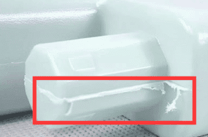
| ● Extra plastic in the form of flakes overflowing from the mold parting surface or insert gap | ● Insufficient clamping force or loose mold closure ● Injection pressure is too high or the melt fluidity is too good (such as too high temperature) ● Mold wear or insufficient processing accuracy | ● Increase clamping force or repair mold mating surface ● Reduce injection pressure, melt temperature or use high viscosity material ● Check mold wear regularly |
| 3 | Vacuum Voids | 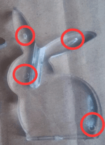
Voids | ● Holes appear inside or on the part surface | ● The melt plastic contains gas (volatiles or air) ● Cooling too quickly, the surface solidifies and the inside shrinks to form a vacuum | ● Increase back pressure and improve the venting system (such as adding venting grooves) ● Reduce injection speed to avoid air inclusion ● Pre-dry hygroscopic materials (such as PA, PET) |
| 4 | Flow Marks | 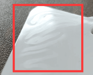
| ● Wavy or radial lines appear on the surface | ● The melt plastics flow front cools too quickly, and the fluidity decreases ● The injection speed is too slow or the mold temperature is too low | ● Increase the injection speed or mold temperature ● Optimize the gate position and shorten the flow path ● Use a material with better fluidity |
| 5 | Silver Streaks | 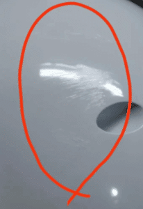
| ● Silver streaks appear on the surface | ● Material degradation (overheating or long residence time) ● Water or volatile matter vaporization | ● Strictly control drying conditions ● Reduce melt temperature or shorten residence time ● Clean the screw rod and barrel to avoid impurities |
| 6 | Short Shot | 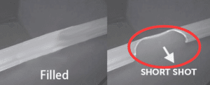
| ● The melt plastics does not completely fill the cavity | ● Insufficient injection volume or pressure ● Excessive flow resistance (gate is too small, mold temperature is too low) ● Poor venting causes gas to hinder filling | ● Increase injection volume, pressure or speed ● Enlarge gate or runner size and increase mold temperature ● Improve venting design |
| 7 | Weld Lines | 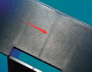
| ● Thin lines formed at the intersection of melts | ● The temperature is too low when the front edges of multiple melts meet ● The gate position or number is unreasonable | ● Increase the mold temperature or melt temperature ● Adjust the gate position or increase the number of gates ● Add venting grooves in the weld mark area |
| 8 | Warpage | 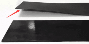
| ● The part bends or twists after cooling | ● Uneven cooling (such as large temperature difference between the upper and lower molds) ● Anisotropic shrinkage (such as fiber-reinforced materials) | ● Optimize the cooling system to ensure uniform cooling ● Adjust the holding pressure or extend the cooling time ● Design ribs or symmetrical structures to balance shrinkage |
| 9 | Black Specks | 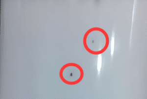
| ● Black impurities appear on the part surface or inside | ● Material degradation or contamination (such as burnt material remaining on the screw rod) ● Mold or barrel not cleaned properly | ● Lower melt temperature to avoid overheating ● Clean the screw rod and mold regularly ● Use materials with better thermal stability |
| 10 | Ejector Marks | 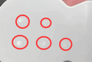
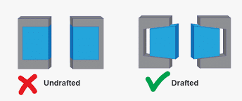
| ● The areas of ejector pin are white or bulging | ● Excessive demoulding force or too fast ejection speed ● Insufficient cooling, the part is too soft | ● Increase the number or area of ejectors and reduce the ejection speed ● Extend the cooling time or reduce the mold temperature ● Optimize the drfat angle or surface polishing |
8. Conclusions
As a mature manufacturing technology, injection molding has been widely used in automobiles, electronics, medical treatment, consumer products, etc.
Despite the maturity of the technology, defects can still occur in production due to slight changes in materials, processes, molds or equipment. This is where Xiamen Eternal Precision comes in – work with us to solve your problems.
Feel free to reach out to us.